LogoLogo
Pinnacle 20|20 Controls
  • Pinnacle 20|20 Controls
    • Overview
    • Home Page
    • Operation
      • Control Page
      • Overview Page
      • Monitor Page
    • System Settings
      • Overview
      • Fan Settings
      • Takeaway Equipment Settings
      • Grain Fill Settings
      • Moisture Sensor Settings
      • Burner Settings
      • Discharge Speed Control
        • Manual Settings
          • Manual Settings Overview
          • Discharge Capacity
          • Incremental Speed Tables
            • 10% Discharge Speed
            • 20% Discharge Speed
            • 30% Discharge Speed
            • 40% Discharge Speed
            • 50% Discharge Speed
            • 60% Discharge Speed
            • 70% Discharge Speed
            • 80% Discharge Speed
            • 90% Discharge Speed
            • 100% Discharge Speed
          • Speed Tables (All-Heat 5pt)
          • Speed Tables (All-Heat 10pt)
          • Speed Tables (Heat+Cool 5pt)
          • Speed Tables (Heat+Cool 10pt)
          • Setting Discharge Speed Operational Limits
          • Setting Mid-Grain Temperature Alarm Limits
        • TruDry Settings
        • AccuDry Settings
          • AccuDry Technology
          • How AccuDry Works
          • Using AccuDry Mode
    • Historical Data
      • Alarm Pop-Ups and History
      • Alarm List
      • Cool Down Alarms
      • Trending
      • Data Logging History
    • Troubleshooting
      • Service
        • TruDry Settings
        • AccuDry Settings
        • Burners Settings
        • HMI Settings
      • Dryer Components
      • System Configuration
      • PLC I/O Modules
        • CPU
        • Digital Inputs / Outputs
        • Analog Inputs
        • Analog Outputs
        • Digital Inputs
        • Analog Inputs / Outputs
      • Safety Circuit
Powered by GitBook
On this page
Export as PDF
  1. Pinnacle 20|20 Controls
  2. Troubleshooting

Safety Circuit

PreviousAnalog Inputs / Outputs

The last of the five options under Troubleshooting is Safety Circuit. The Safety Circuit page gives an illustration of the components within the safety circuit and their status.
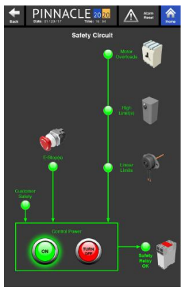
Again, this screen will look slightly different from dryer model to dryer model given the components that are equipped or not equipped on the dryer. From this page, Control Power can be turned on or off, just as it can be from the Control Page. However, if the safety circuit is not satisfied, Control Power will not be able to be turned on.

Components with green globes next to them indicate components that are good and satisfying that part of the safety circuit. However, if a globe next to the component appears grayed out as opposed to green, that indicates that there is a break in the safety circuit at that particular component. Furthermore, if there is an issue with a component, all components downstream will appear grayed out as well. It is best to check the component that is first in line where the globe is gray. For instance, if the motor overloads are grayed out, the high limits and linear limits (if equipped) will appear grayed out as well. First start troubleshooting the motor overloads, which are upstream from the High Limits and Linear Limits. It is very likely once the issue with the motor overloads are solved, the all other components downstream will glow green as well, satisfying the safety circuit. If not, move on to the next grayed out component downstream and troubleshoot.