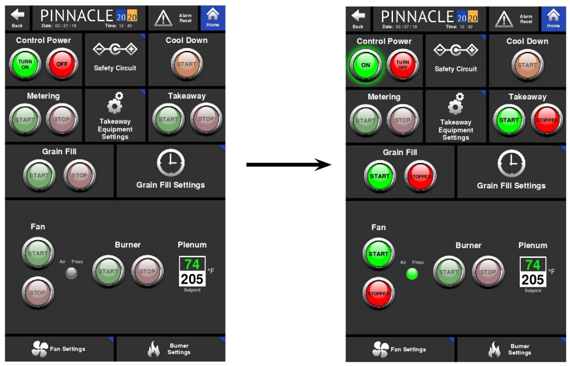
Control Page
When first starting the dryer, the Control page will need to be accessed. The Control page layout differs slightly from dryer model to dryer model. It is here where the Control Power, Grain Fill, Discharge, Fan, Blowers, and Burners can all be started from the same page. Each function such as Grain Fill, Discharge, Fans & Burners are grouped in boxes or tiles. It is within these tiles where the associated command buttons are located. The green buttons are "START" or "ON" buttons while the red buttons are "STOP" or "OFF" buttons. These command buttons are designed to communicate to the operator the feature's status and available function by way of color and text within the button. For a pair of buttons, one will have text within it that reads the status (ON, OFF, or RUNNING) while the other button will have text that reads the available command (TURN OFF, TURN ON, or STOP). The text and color within and around the buttons change as the status and available function changes.
Control Power
Shown below is the Control page for a tower or an all-heat ECO dryer. Before any function on the Control page can be performed, the Control Power must first be on. To turn Control Power on, simply press the green "TURN ON" button within the Control Power tile. There should be a slight delay while the safety circuit verifies satisfactory conditions. During this slight delay, the text within that same button should read "TURNING ON". If Control Power is achieved, the text within that same green button should then read "ON", a green glow should surround the button, and the text within the red button will change from "OFF" to "TURN OFF".

Failure to get Control Power will require troubleshooting. An initial place to troubleshoot for this would be the safety circuit. Reference the troubleshooting portion of this manual for more information.
Similarly, to turn Control Power off, press the associated red button that reads "TURN OFF" and the text within that button should change to "OFF" and the text within the associated green button should change from "ON" to "TURN ON", and the surrounding green glow should disappear.
Fans and Burners
Once Control Power is on and there are no other issues preventing the starting of the other features, the dimly lit buttons will illuminate signaling that they are ready to start. Dimly lit buttons signify those features that are equipped on the dryer. Fully illuminated buttons are for features that are ready to be started or turned on. Those buttons that appear gray, are simply place holders for features that are not currently installed on the dryer. Below is an example of a Legacy Control page where the number of fans and burners vary depending on the model. For this reason, the Control page layout varies from model to model. Shown below is the Control page for a 2 burner Legacy dryer. Since the dryer is equipped with only 2 fans and 2 burners, controls for plenums 1 and 2 are illuminated while plenums 3 and 4 are greyed out.
With Control Power on and the Fan Start buttons fully illuminated, the fans are ready to start. Starting the fans is the same as turning Control Power on. The green buttons activate while the red buttons deactivate. Both buttons communicate the status as well as control the function.

Notice the burner buttons are dimly lit. Dimly lit buttons signify features that are equipped on the dryer, but are not ready to be started or turned on. The burner buttons will not fully illuminate or be ready to start until the fans are running and air pressure is present. Once the fan status is "RUNNING" with a green glow surrounding the Start button and the air pressure is satisfied as illustrated with a green illuminated indicator, the burners can be started. Again, the buttons will communicate the available command and current status. For the burners, the start process is more complicated and it involves purging and trial for ignition. While the burners attempt to ignite, the associated buttons will communicate the current status of the ignition process via text within the buttons.

Next to each set of burner control buttons are read and write boxes. The read box in green text is the real time temperature inside that particular plenum. The white, write box, is where the operator can enter the desired temperature for that particular plenum.
Grain Fill, Discharge and Metering
The Grain Fill, Discharge and Metering tiles all contain control buttons to stop and start the fill, discharge, and metering motors. These buttons act in the same way as the rest of the buttons on the Control page by communicating the available function and current status.
Cool Down
The Cool Down function allows for a graceful shutdown of the dryer. More on this function is explained in the Cool Down Alarms section of this manual.
Quick Launches
As mentioned in the Introduction of this manual, there are quick launch buttons throughout the software. The quick launch buttons allow the operator quick access to more in depth information and settings. They are typically located in ideal places where the subject matter of the quick launch is associated with a nearby function. On the Control page, the Safety Circuit quick launch is located next to the Control Power tile since issues with getting Control Power may be associated with a break in the Safety Circuit. Similarly, quick launches for the Grain Fill and Takeaway Equipment Settings are located next to the Grain Fill and Discharge tiles. Further details on these quick launch pages and their contents are explained in the System Settings, Historical Data and Troubleshooting chapters.
Last updated
