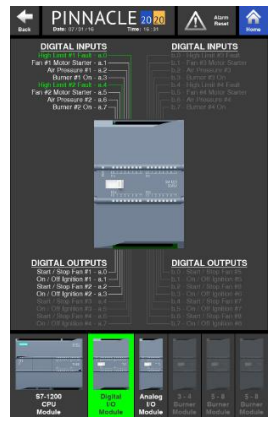
Digital Inputs / Outputs
The next selection at the bottom of the page is an I/O module, allowing up to 16 digital inputs and 16 digital outputs.

16 Digital Inputs
Ia.0
High Limit #1 Fault
Green indicates that the high limit circuit is complete and is functioning properly for burner 1. White indicates that the high limit setpoint has been reached for burner 1, tripping the high limit switch.
Ia.1
Fan #1 Motor Starter
Green indicates that the auxiliary contact for fan 1 motor starter is ON. If white, it is OFF.
Ia.2
Air Pressure #1
Green indicates that air pressure switch for plenum 1 has been activated and the blower for that plenum is generating sufficient pressure. White indicates low or no pressure.
Ia.3
Burner #1 On
A green signal verifies that a flame is present at burner 1. White signifies the absence of flame.
Ia.4
High Limit #2 Fault
Green indicates that the high limit circuit is complete and is functioning properly for burner 2. White indicates that the high limit setpoint has been reached for burner 2, tripping the high limit switch.
Ia.5
Fan #2 Motor Starter
Green indicates that the auxiliary contact for fan 2 motor starter is ON. If white, it is OFF.
Ia.6
Air Pressure #2
Green indicates that air pressure switch for plenum 2 has been activated and the blower for that plenum is generating sufficient pressure. White indicates low or no pressure.
Ia.7
Burner #2 On
A green signal verifies that a flame is present at burner 2. White signifies the absence of flame.
Ib.0
High Limit #3 Fault
Green indicates that the high limit circuit is complete and is functioning properly for burner 3. White indicates that the high limit setpoint has been reached for burner 3, tripping the high limit switch.
Ib.1
Fan #3 Motor Starter
Green indicates that the auxiliary contact for fan 3 motor starter is ON. If white, it is OFF.
Ib.2
Air Pressure #3
Green indicates that air pressure switch for plenum 3 has been activated and the blower for that plenum is generating sufficient pressure. White indicates low or no pressure.
Ib.3
Burner #3 On
A green signal verifies that a flame is present at burner 3. White signifies the absence of flame.
Ib.4
High Limit #4 Fault
Green indicates that the high limit circuit is complete and is functioning properly for burner 4. White indicates that the high limit setpoint has been reached for burner 4, tripping the high limit switch.
Ib.5
Fan #4 Motor Starter
Green indicates that the auxiliary contact for fan 4 motor starter is ON. If white, it is OFF.
Ib.6
Air Pressure #4
Green indicates that air pressure switch for plenum 4 has been activated and the blower for that plenum is generating sufficient pressure. White indicates low or no pressure.
Ib.7
Burner #4
On A green signal verifies that a flame is present at burner 4. White signifies the absence of flame.
16 Digital Outputs
Qa.0
Start / Stop Fan #1
Green indicates that fan 1 motor has been commanded to run. White indicates that it has not been commanded to run.
Qa.1
On / Off Ignition #1
Green indicates that burner 1 has been commanded to ignite and will stay ON while operating. White indicates that it is OFF.
Qa.2
Start / Stop Fan #2
Green indicates that fan 2 motor has been commanded to run. White indicates that it has not been commanded to run.
Qa.3
On / Off Ignition #2
Green indicates that burner 2 has been commanded to ignite and will stay ON while operating. White indicates that it is OFF.
Qa.4
Start / Stop Fan #3
Green indicates that fan 3 motor has been commanded to run. White indicates that it has not been commanded to run.
Qa.5
On / Off Ignition #3
Green indicates that burner 3 has been commanded to ignite and will stay ON while operating. White indicates that it is OFF.
Qa.6
Start / Stop Fan #4
Green indicates that fan 4 motor has been commanded to run. White indicates that it has not been commanded to run.
Qa.7
On / Off Ignition #4
Green indicates that burner 4 has been commanded to ignite and will stay ON while operating. White indicates that it is OFF.
Qb.0
Start / Stop Fan #5
Green indicates that fan 5 motor has been commanded to run. White indicates that it has not been commanded to run.
Qb.1
On / Off Ignition #5
Green indicates that burner 5 has been commanded to ignite and will stay ON while operating. White indicates that it is OFF.
Qb.2
Start / Stop Fan #6
Green indicates that fan 6 motor has been commanded to run. White indicates that it has not been commanded to run.
Qb.3
On / Off Ignition #6
Green indicates that burner 6 has been commanded to ignite and will stay ON while operating. White indicates that it is OFF.
Qb.4
Start / Stop Fan #7
Green indicates that fan 7 motor has been commanded to run. White indicates that it has not been commanded to run.
Qb.5
On / Off Ignition #7
Green indicates that burner 7 has been commanded to ignite and will stay ON while operating. White indicates that it is OFF.
Qb.6
Start / Stop Fan #8
Green indicates that fan 8 motor has been commanded to run. White indicates that it has not been commanded to run.
Qb.7
On / Off Ignition #8
Green indicates that burner 8 has been commanded to ignite and will stay ON while operating. White indicates that it is OFF.
