Dryer Components
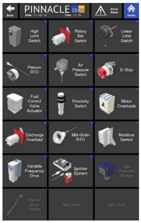
The second of the five options under Troubleshooting is Dryer Components. This page allows the user to quickly understand a dryer components function and perhaps, how to set it if necessary.
Only the components that are equipped on the dryer will appear on this screen. If a particular component is not equipped on the dryer, it will appear grayed out on this page.

Clicking on any of the component tiles will bring up a screen, detailing the purpose and function of that component.

A brief description of the components listed on the dryer components page is as follows:
High Limit Switch
The High Limit Switch utilizes a capillary bulb to sense an over-temperature condition in the plenum which will cause the dryer to shutdown. The high limit setpoint is adjustable on the switch and should be set approximately 40 deg F higher than the plenum temperature setpoint.
Rotary (Bin) Fill Switch
The Rotary Fill Switch is located in the wet hopper and is powered by 24VDC. The switch is motorized and will rotate a paddle until wet grain comes in contact with the paddle. Once this happens, grain stops the rotation and proves the level of grain in the hopper.
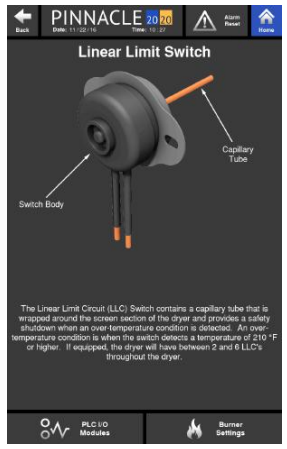
Linear Limit Circuit (LLC) Switch (if equipped)
The Linear Limit Circuit (LLC) Switch is wrapped around the screen section of the dryer and provides a safety shutdown when over-temperature is detected.
Plenum RTD
The Plenum RTD is a temperature sensing device located in the plenum used to send a signal to the PLC to establish and maintain plenum temperature.
Air Pressure Switch
The purpose of the Air Pressure Switch is to prove airflow from the fan for safe operation of the burner. The air pressure switch is adjustable and should be set once the dryer is full of grain. Adjustment of the switch for a profile dryer is done in the burner control cabinet and indication of reaching the air pressure switch's setpoint is indicated on the green light on the outside of the burner control cabinet. For a tower dryer, adjustment of the switch is done in the High Voltage Cabinet and is indicated on the green light on the outside of the High Voltage Cabinet.
E-Stop
The E-Stop buttons are located throughout the dryer and are used to trip the safety circuit and shutdown the dryer when pressed. To reset a pressed E-stop button, simply rotate the spring loaded red button clockwise.
Control Valve Actuator
The Control Valve Actuator is an electrical actuator that is connected to the control valve through a mechanical linkage that precisely positions it based on the output of the PLC. As the plenum temperature drops below the setpoint, the PLC tells the control valve actuator to open more, whereas if the plenum temperature rises above the setpoint, the PLC tells the control valve actuator to close more.
Proximity Switch
The Proximity Switch is used to detect the rotation of the discharge metering system by sensing the proximity of a detector on the discharge metering shaft of profiles and sweep motor for towers. If the rotation goes undetected for a set duration of time, the machine will be shutdown.
Motor Overloads
The Motor Overloads are located in the high voltage cabinet and are used to protect the motors from excessive current. When excessive current draw is detected, the Motor Overload will trip, cutting power to the motor and protecting it.
Discharge Limit Switch
The type of Discharge Limit Switch used depends on the type of dryer; Tower or Profile. The towers use the same paddle style as the Rotary Fill Switch while the Profile dryers use a whisker style switch as shown on the left. The purpose of this switch is to detect a discharge grain overload condition that may be a result of a failed discharge auger or takeaway equipment. Once an overload conditions exists, the safety circuit is opened and the dryer is shutdown.
Mid-Grain RTD Assembly
The two Mid-Grain RTD (Resistance Temperature Device) Assemblies are located around the perimeter of the dryer and are used to detect the temperature of the grain in the column. Each of these two RTD assemblies is equipped with a 4-20mA transmitter which provides an analog input signal sent to the PLC.
DM510 Moisture Sensor
This sensor has a stainless steel fin that measures the grain moisture indirectly by measuring the capacitance of the field of grain and correlating it to a voltage. It also contains a small temperature probe that is mounted directly under the stainless steel fin on the face of the sensor. This probe also produces an analog voltage measurement of the grain's temperature to compensate the moisture reading and to provide a real-time indication of the grain's temperature.
Variable Frequency Drive (VFD)
The VFDs are used to control the speed of the metering and takeaway system and are directly controlled by the PLC.
Ignition System
The Ignition System is comprised of different components, each playing a role in the management of the burners. The Ignition System controls the overall operation of the burners by supplying high voltage from the coils to the spark plugs to ignite the burners, sending signals to open/close the gas valves, and continuously monitoring the presence of a flame for safe and reliable operation.
Gas Pressure Switch
These switches are used to detect either low gas or high gas pressure in the gas train and shutdown the dryer if required.
Plenum Door Switch
The Plenum Door Switch is used to trip the safety circuit, shutting the dryer down in the event a plenum door is opened.
