Operation
This section of the manual provides information on the operation of the Pinnacle 20|20 dryer control system.
Control Page
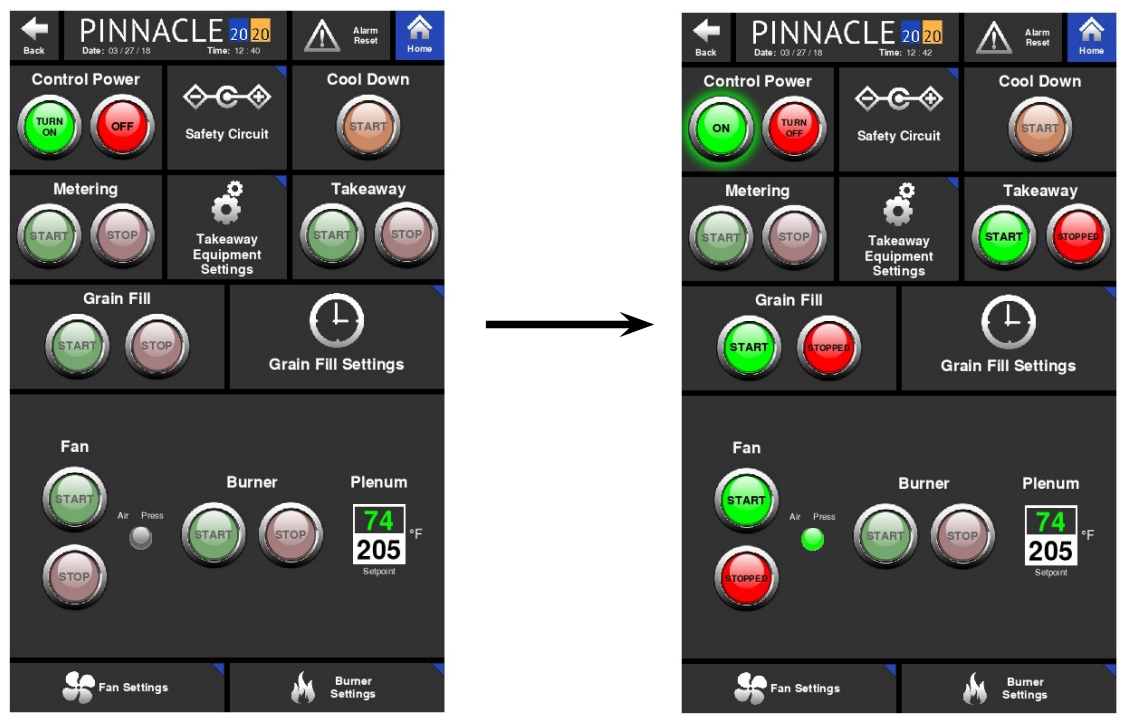
When first starting the dryer, the Control page will need to be accessed. The Control page layout differs slightly from dryer model to dryer model. It is here where the Control Power, Grain Fill, Discharge, Fan, Blowers, and Burners can all be started from the same page. Each function such as Grain Fill, Discharge, Fans & Burners are grouped in boxes or tiles. It is within these tiles where the associated command buttons are located. The green buttons are "START" or "ON" buttons while the red buttons are "STOP" or "OFF" buttons. These command buttons are designed to communicate to the operator the feature's status and available function by way of color and text within the button. For a pair of buttons, one will have text within it that reads the status (ON, OFF, or RUNNING) while the other button will have text that reads the available command (TURN OFF, TURN ON, or STOP). The text and color within and around the buttons change as the status and available function changes.
Control Power
Shown below is the Control page for a tower or an all-heat ECO dryer. Before any function on the Control page can be performed, the Control Power must first be on. To turn Control Power on, simply press the green "TURN ON" button within the Control Power tile. There should be a slight delay while the safety circuit verifies satisfactory conditions. During this slight delay, the text within that same button should read "TURNING ON". If Control Power is achieved, the text within that same green button should then read "ON", a green glow should surround the button, and the text within the red button will change from "OFF" to "TURN OFF".

Similarly, to turn Control Power off, press the associated red button that reads "TURN OFF" and the text within that button should change to "OFF" and the text within the associated green button should change from "ON" to "TURN ON", and the surrounding green glow should disappear.
Fans and Burners
Once Control Power is on and there are no other issues preventing the starting of the other features, the dimly lit buttons will illuminate signaling that they are ready to start. Dimly lit buttons signify those features that are equipped on the dryer. Fully illuminated buttons are for features that are ready to be started or turned on. Those buttons that appear gray, are simply place holders for features that are not currently installed on the dryer. Below is an example of a Legacy Control page where the number of fans and burners vary depending on the model. For this reason, the Control page layout varies from model to model. Shown below is the Control page for a 2 burner Legacy dryer. Since the dryer is equipped with only 2 fans and 2 burners, controls for plenums 1 and 2 are illuminated while plenums 3 and 4 are greyed out.
With Control Power on and the Fan Start buttons fully illuminated, the fans are ready to start. Starting the fans is the same as turning Control Power on. The green buttons activate while the red buttons deactivate. Both buttons communicate the status as well as control the function.

Notice the burner buttons are dimly lit. Dimly lit buttons signify features that are equipped on the dryer, but are not ready to be started or turned on. The burner buttons will not fully illuminate or be ready to start until the fans are running and air pressure is present. Once the fan status is "RUNNING" with a green glow surrounding the Start button and the air pressure is satisfied as illustrated with a green illuminated indicator, the burners can be started. Again, the buttons will communicate the available command and current status. For the burners, the start process is more complicated and it involves purging and trial for ignition. While the burners attempt to ignite, the associated buttons will communicate the current status of the ignition process via text within the buttons.

Next to each set of burner control buttons are read and write boxes. The read box in green text is the real time temperature inside that particular plenum. The white, write box, is where the operator can enter the desired temperature for that particular plenum.
Grain Fill, Discharge and Metering
The Grain Fill, Discharge and Metering tiles all contain control buttons to stop and start the fill, discharge, and metering motors. These buttons act in the same way as the rest of the buttons on the Control page by communicating the available function and current status.
Cool Down
The Cool Down function allows for a graceful shutdown of the dryer. More on this function is explained in the Cool Down Alarms section of this manual.
Quick Launches
As mentioned in the Introduction of this manual, there are quick launch buttons throughout the software. The quick launch buttons allow the operator quick access to more in depth information and settings. They are typically located in ideal places where the subject matter of the quick launch is associated with a nearby function. On the Control page, the Safety Circuit quick launch is located next to the Control Power tile since issues with getting Control Power may be associated with a break in the Safety Circuit. Similarly, quick launches for the Grain Fill and Takeaway Equipment Settings are located next to the Grain Fill and Discharge tiles. Further details on these quick launch pages and their contents are explained in the System Settings, Historical Data and Troubleshooting chapters.
Overview Page
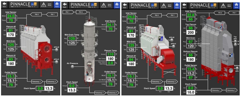
The Overview page is the second page of the three Operation pages. The Overview page provides the operator with a full rendering of the dryer that, with the use of different graphics, illustrates what components of the dryer are operating. The Overview page is unique to match the particular dryer that is loaded on the Pinnacle 20|20. The images below show the different Overview pages for a Legacy, Tower, ECO, and Delta dryer. In the Overview pages, shown below, none of the dryer components (motors, burners, etc.) are running.

Graphic Explanation
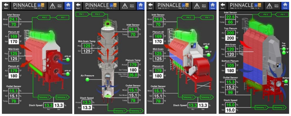
The Overview page will change when different operations/features are running or turned off. The different graphics and their meaning are as follows:
Blue arrows
Indicate a fan is running.
Red arrows
Indicate a fan and burner are both running.
Blue and white burner flame
Only shown on tower dryers to further indicate the burner is on.
Blue plenum with blue arrows
Indicate a cooling plenum with the fan running.
Red plenum with red arrows
Indicate a heating plenum with the fan running and the burner on.
Sweep flashes green
Only shown on tower dryers to indicate the sweep is turning.
Area housing metering rolls flash green
Only shown on profile and mixed flow dryers to indicate the metering rolls are turning.
Hopper glows green
The fill is on.
Hopper flashes
Level auger is running.
Green air pressure indicator
Air pressure switch is satisfied.
Gray air pressure indicator
Air pressure switch is not satisfied.
Fill and Takeaway
In addition to these graphics, there are lines shown leading to the hopper and from the discharge. The line leading to the hopper contains two tags: Fill 1 and Fill 2. When the line is white, the fill cycle is off.
When the line is green, the fill cycle is on. When any of the tags blink, that particular part of the fill cycle is running. So while the Fill 1 or Fill 2 tags are green, but not blinking, it means it's enabled but currently not running. Only when it blinks does it mean that that particular portion, the Fill 1 or Fill 2, of the fill cycle is actually running. It is the same for the line exiting the discharge. When this line is white, it means the discharge is off. When the line is green, it means the discharge is on. A blinking Takeaway 1 or Takeaway 2 tag indicates that the Takeaway 1 or Takeaway 2, whichever is blinking, is currently running. A solid green Takeaway 1 or Takeaway 2 tag simply means it is enabled but not currently running.

Read and Write Values
The Overview page also contains information on the real-time plenum temperature, discharge speed, and if equipped, the values from the inlet and outlet sensors. The values in green text are the actual values being read. The values shown in a white box with black text are desired or "Set" values that can be changed by the operator. The ability to adjust the "Set" values associated with Mid-Grain Temp, Discharge Speed, and Outlet Sensor Moisture is dependent on the selected discharge mode. If Manual mode is selected, the Discharge Speed "Set" value will be able to be adjusted. If TruDry is selected, the Mid-Grain Temp "Set" value will be able to be adjusted. Finally, if AccuDry is selected, the Outlet Sensor "Set Moist" value, which is the desired outlet grain moisture, will be able to be adjusted. One value that can always be adjusted, regardless of selected discharge mode, is the plenum temperature(s).
Monitor Page
Discharge Information
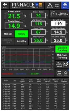
The Monitor Page is the third of the three Operation pages. The Monitor page is divided into thirds. The top third contains quantitative values that can either be read or adjusted. The operator can also change between discharge modes from here. However, it is important to note that when changing between TruDry and AccuDry, the operator must change to Manual mode first before changing to TruDry or AccuDry.
Another area where the operator can change discharge modes and make adjustments to the discharge settings is in the Discharge Speed Control quick launch. More on the contents within the Discharge Speed Control page can be viewed in the associated section.

Trending Graphs
In the middle of the Monitor page a quick view of different trending graphs is displayed. The graph shows up to 2 hours of recorded data. The operator can choose which trending graph to display on the Monitor page by selecting either the Moisture Trending button or Mid-Grain Trending button. Selecting these buttons will cause the display to toggle between these two graphs. The button highlighted in green indicates the graph that is currently being displayed on the Monitor page.
If more information about the trending graphs is desired, the operator can quickly access it by simply pressing the "More Trending Options" button. This quick launch contains larger graphs, with more information which is further explained in the Trending section of this manual.
Running Data
The bottom third of the Monitor page is where a table containing historical running data is displayed. The data displayed is grouped into rows that correspond to a date and time at which those values were recorded. A row of data is recorded every 10 minutes, spanning a total of two hours. The data that makes up this two hour graph is collected whether the dryer is discharging or not. More data can be accessed by pressing the More Data History quick launch button. Additional explanation can be found in the Data Logging History section.